Building from scratch a piano-like electronic instrument
Introduction
In this document I describe various aspects of my project which was designing and building from scratch a piano-like electronic instrument. The goals, the design, the creation process, the challenges, and so on.
Please watch the video for a quick overview:
klavirko.mp4
The video is in Polish language but subtitles are available:
klavirko-english.vtt
klavirko-polish.vtt
The video is also available on youtube, with subtitles too (https://youtu.be/fG8-jLbbbjQ).
It is much less serious than this document.
Goals and requirements
The main goal of this project was to build this instrument by myself. I defined some requirements:
- 5 octaves (61 keys) on the physical keyboard, with possibility to easily transpose up or down
- keys working on-off only, no detection of velocity, pressure
- polyphony, be able to play more notes than there are fingers
- definable waveform and envelope
- reuse the user interface board from the washing machine
- originally I didn't plan for all the potentiometers but I changed my mind as it would not be comfortable to change those things from the menu
- MIDI support was considered as an option
Keyboard
I had the dream to build my own instrument for a few years already. But for a long time I had no idea how to build the keyboard. Any other part of the instrument could be made of available elements but the keyboard is an exception.
I considered multiple things:
- I asked in music shops if they are also selling just the keyboards and not only the entire instruments. They weren't.
- I also looked on the Internet for electronic piano keyboards. I only found very expensive ones. I also found some replacement keys but usually it was just the plastic part and the spring and also expensive.
- Description of some other people's projects says that they took keyboards from existing old instruments. I didn't want to do this. I wouldn't feel good about destroying an instrument to built mine.
- I tried to look for advertisements if maybe someone is trying to sell damaged instruments. I wouldn't have a problem with destroying an instrument that is already broken. Unfortunately I did not find anything.
- I considered getting the keyboard from a cheap toy piano. Unfortunately for toys the quality is terrible and the keys are too small.
- I did not believe that I would be able to build a keyboard mechanism by myself.
At some point I saw a video on youtube (https://youtu.be/7GiC8NTZ6sE) which shows how someone (Ronald Walters) built a keyboard. This was a breakthrough. I realised that this is something that I am actually able to build. Not with such a precision as on the video because I don't have such advanced tools but still doable.
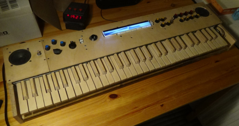
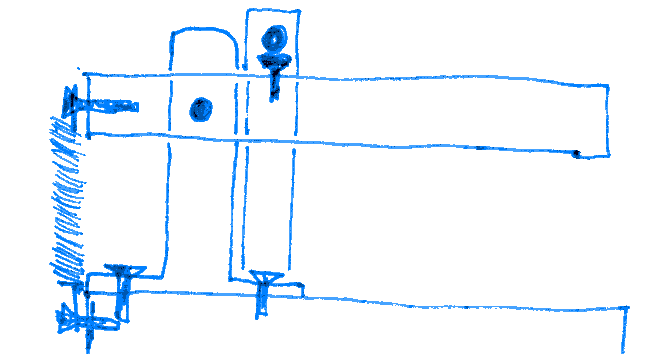
The design is this:
A rectangular block is the key.
A perpendicular hole is the axis of rotation.
The spring behind is keeping the key in horizontal position.
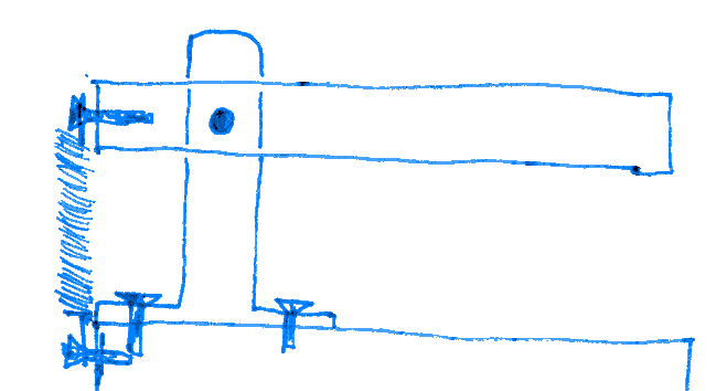
A finger press moves the key down.
After release, it moves back up.
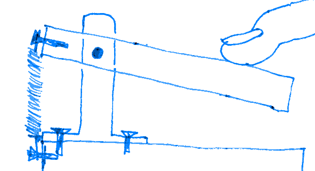
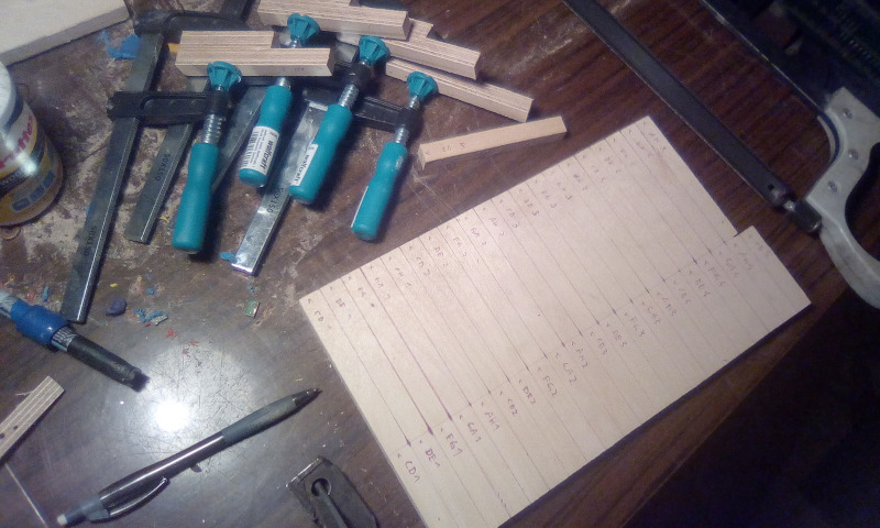
After the design another thing I needed were the dimensions for the keys.
Did you know that it is impossible to build a "perfect" keyboard?
It is not possible to perfectly divide the width of an octave so that all white keys are equal, all black keys are equal, and all spaces between black keys are equal to each other and to the black keys.
This page (http://quadibloc.com/other/cnv05.htm) contains a detailed description and provides a practical solution which I used:
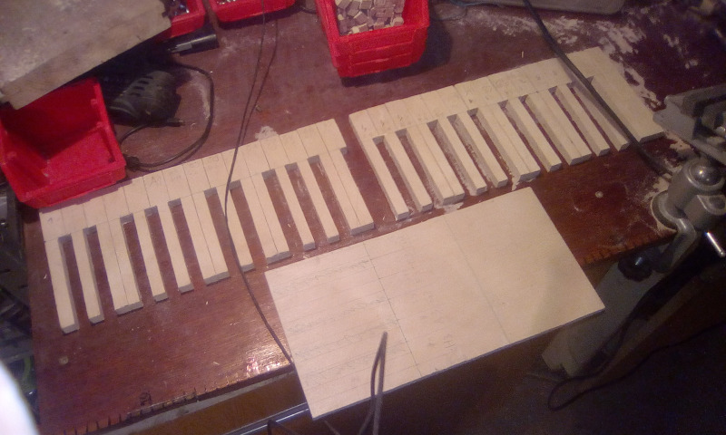
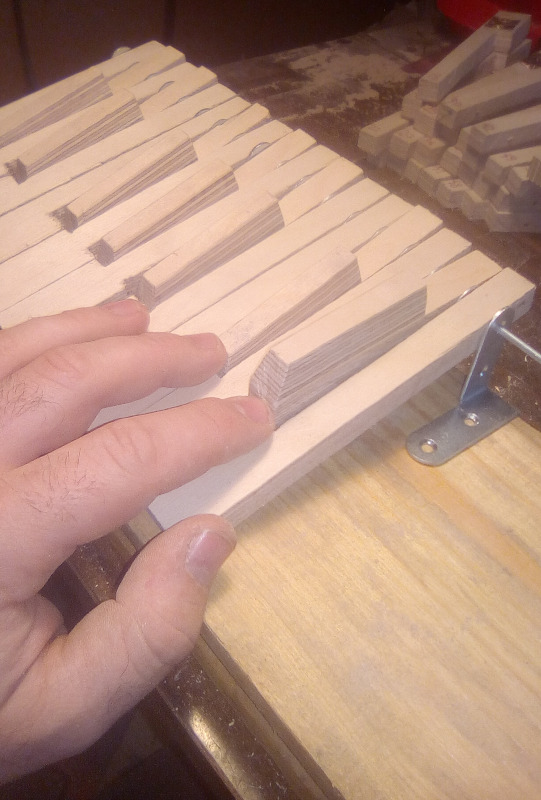
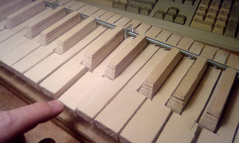
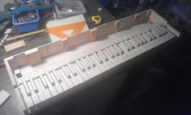
I cut the keys from 12mm plywood. For black keys I cut 2 pieces and glue them together.
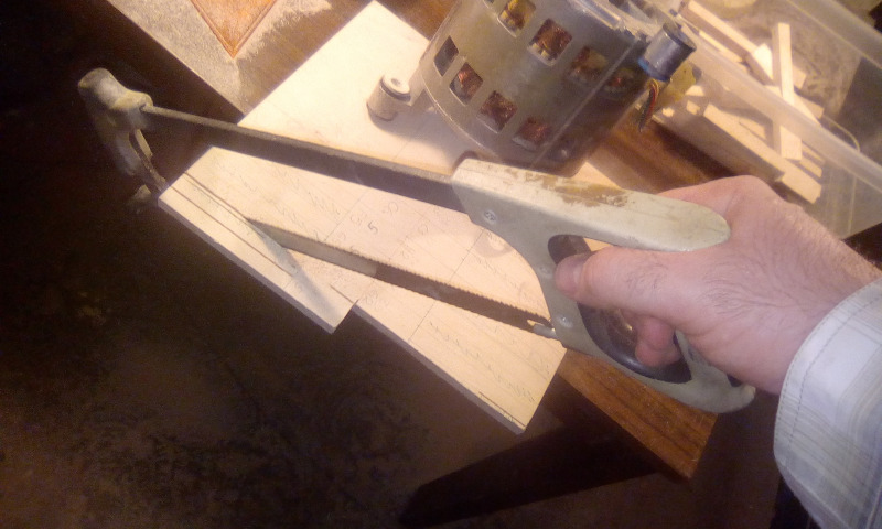
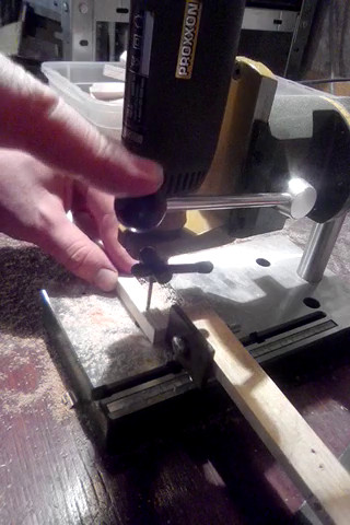
Each key needs a hole drilled, for the axis of rotation.
It is important to make the hole as precise as possible, especially the hole must be as perpendicular as possible. because of the key's dimensions any inprecision on this end will be amplified on the other end.
That's why I had to use a guiding device for the drill. I would not be able to do it well enough by hand.
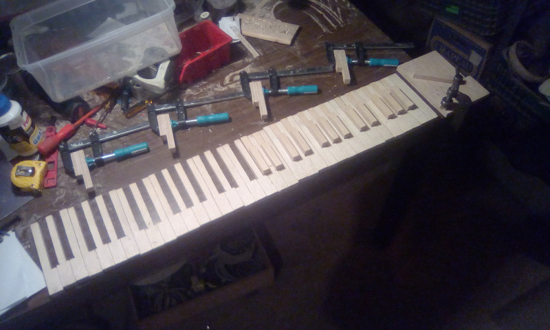
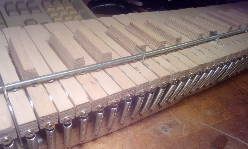
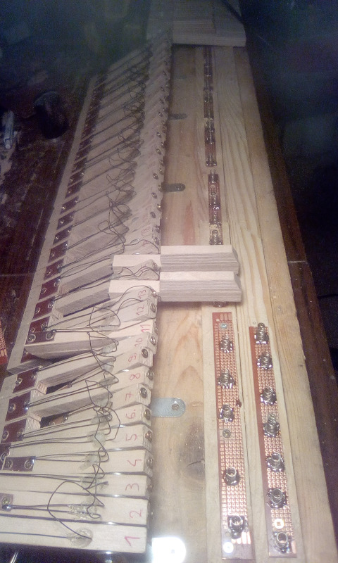
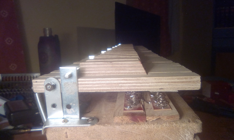
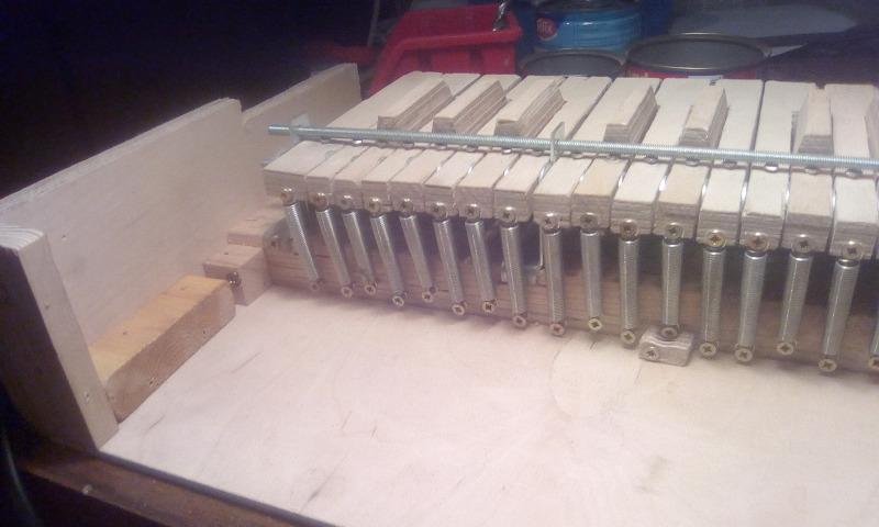
A horizontal rod is inserted through all keys. Between each key is a metal washer to keep distance. Every 9 or 8 keys there is an additional support for the rod.
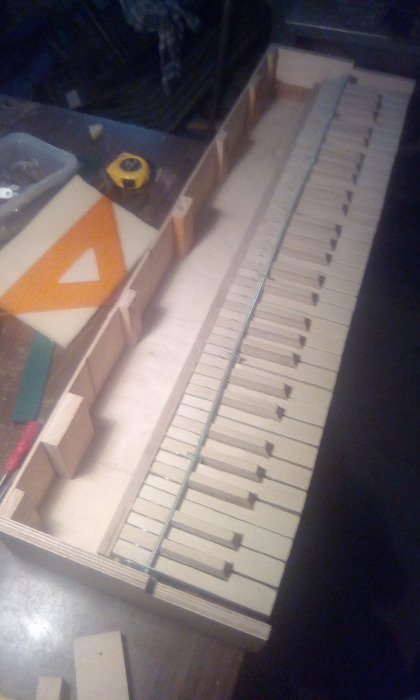
The keys when not pressed should remain in a horizontal position, all aligned with each other so that they form a single plane. This was more challenging than I originally expected. I cannot simply rely on the springs only to keep the required position. Instead the springs must try to move the key even more upwards but something else should block the keys from going there. The blocking point must be close to the axis of rotation to not also block the fingers. But this means that again at the end of the key any inprecision will be amplified multiple times.
I wasted much time building a mechanism that was terrible and didn't work.
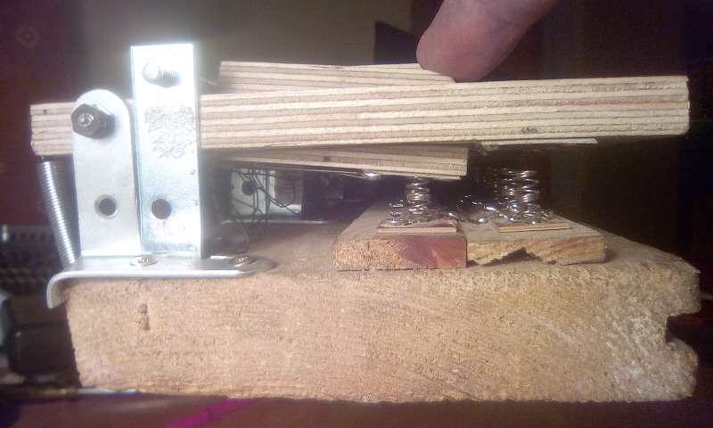
But later I made something that did work. This is the updated design:
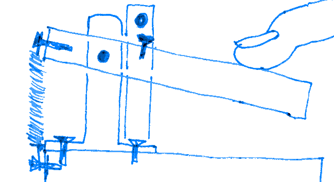
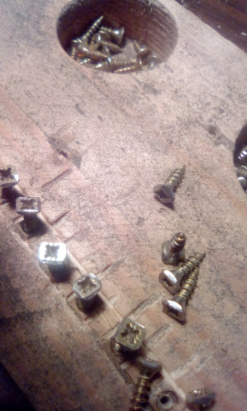
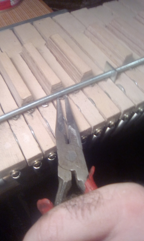
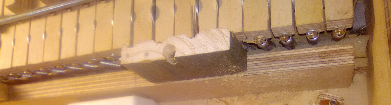
Now there is not only a single perpendicular horizontal rod which is the axis of rotation but there is a second one above the keys which stops them from moving too far upwards. In each key there is a small screw which defines the stopping position. Turning the screw adjusts the position. But there is another challenge. I can't use a screwdriver because of the rod.
So each screw's head is cut into a square which allows to grab them from behind and rotate.
With this the mechanism is complete. But the pressed key must close (or open) an electric circuit otherwise it is useless. So here comes another update of the design:
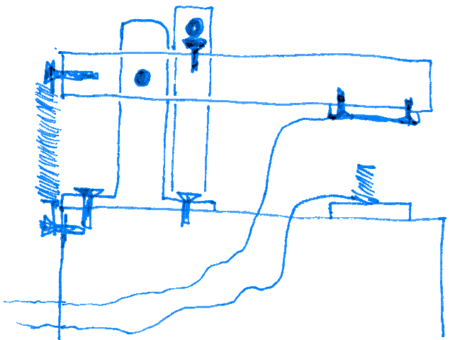
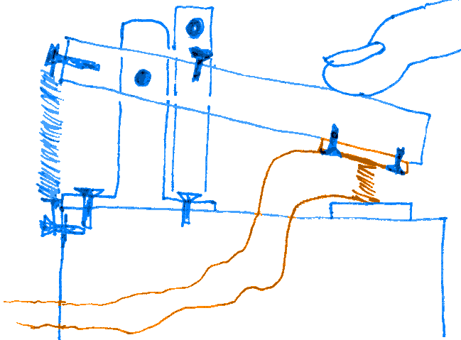
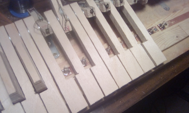
On the underside of each key there is attached a rectangle cut from a board for making PCB, so covered with a layer of copper from one side.
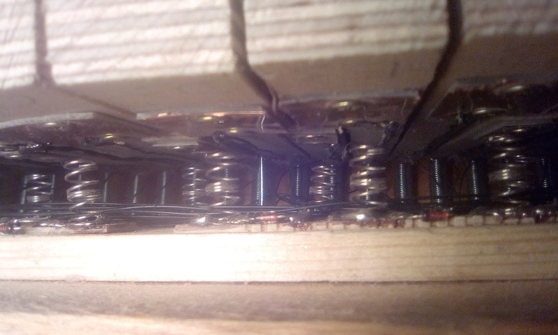
Below each key there is a metal spring. Both the spring and the rectangle have wires soldered. When the key is pressed both elements touch each other and close the circuit. Additionally the spring stops the key from hitting the floor.
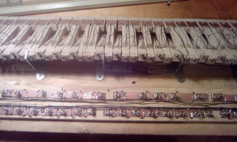
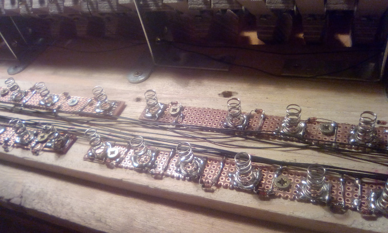
There is another challenge: where do I get the springs? It's not very difficult to buy metal springs but I need springs which can be soldered. Normal strings can not. What I used were springs for capacitive touch sensors. But I still don't know where to buy them. In shops selling electronic components I did not find any. When I asked some people about it I simply received the springs that I needed from someone which is great for this project but does not answer the question. If you do know where to buy solderable springs (without having to buy thousands of them) please let me know.
(And if you know where to buy reasonably priced keys for electronic keyboard instruments then also please let me know.)
Keyboard circuit
The keys have to be connected to a controller somehow. There are multiple ways of wiring a keyboard. If you want to read about the multiple possibilities then this page (http://www.openmusiclabs.com/learning/digital/input-matrix-scanning/index.html) is a good recommendation. I made the very popular choice of a simple matrix with diodes.
I have 61 keys so the most optimal way of wiring would be an 8 by 8 matrix which allows for 64 keys. But that's not what I did. The keyboard has 5 octaves but I want it to support 8 octaves with a way to select which 5 of the 8 are active. And I want the octave switching to be done entirely in hardware. So it makes sense to group the keys in full octaves.
So I use a 6 by 12 matrix, with 5 groups of 12 keys and 1 group of 1 key.
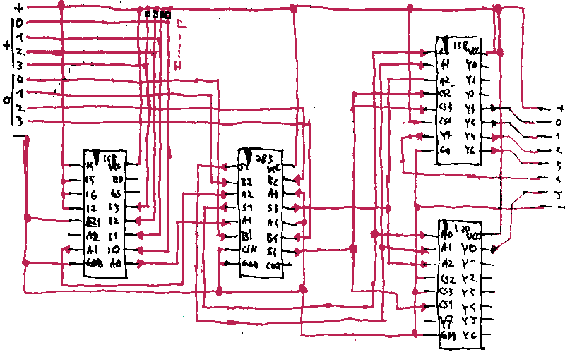
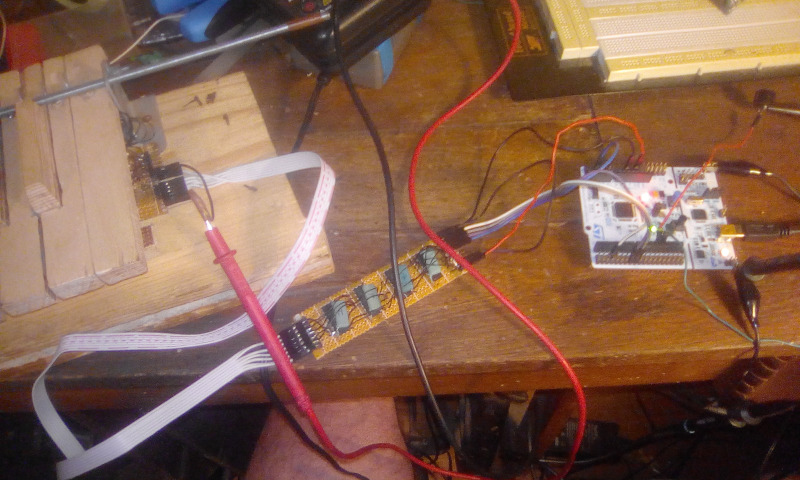
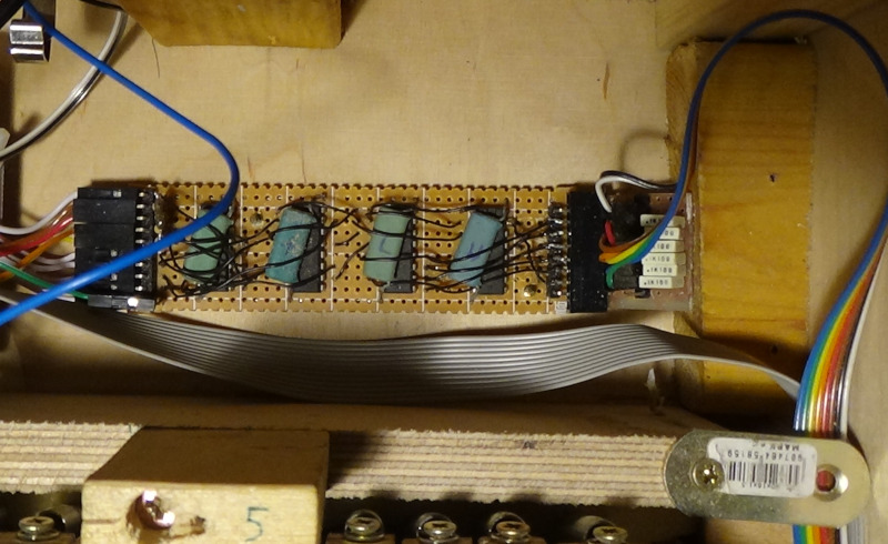
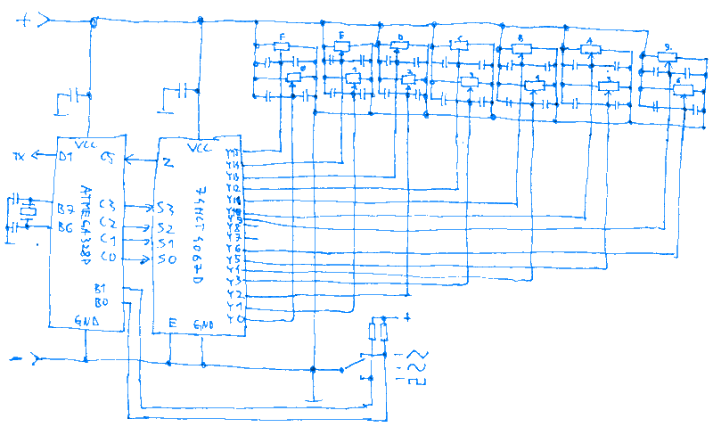
This is my circuit and how it works:
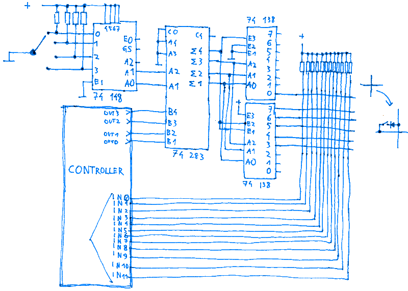
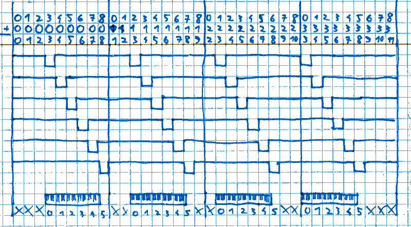
The controller outputs a 16 bit number which represents the currently active octave. The number is quickly changing in this seruence:
... 0 1 2 3 4 5 6 7 8 0 1 2 3 4 5 6 7 8 0 1 2 3 4 5 6 7 8 ...
A 4 position switch is the octave selector. The 74148 encodes its position into a 2 bit number with possible values of 0 1 2 3.
The 74283 then adds this number to the controller's output.
The result is then decoded by the 74138 to signals controlling the physical octaves. whenever the result is 3 the first octave is in a low state, the second octave when it's 4 and so on. The low state can go through the diode and reach the controller's input if the relevant key is pressed. As seen here the octave selector shifts the signals in time which changes which physical octave is matched to which logical octave. This way the octave switching is done entirely in hardware. The software is completely unaware of any of this and is always controlling a full 8 octave (+1 key) keyboard.
Controller
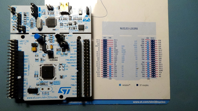
I decided that the sound is generated by software. So I need some kind of microcontroller to read the keyboard, generate the sound and so on. I chose to use the board ST Nucleo-L053R8 which contains the STM32L053R8T6 microcontroller (https://www.st.com/en/evaluation-tools/nucleo-l053r8.html). Important factors for this choice:
- it has enough I/O pins available
- the multiplication instruction is performed in a single clock cycle
- I already had two of those at home
Sound generation
There is a sampling frequency of 44.444...kHz. The generator has 12 separate channels. Each channel can have its own pitch and envelope. The waveform and envelope properties are the same for each channel.
Every 720 cycles of the 32MHz main clock there is an interrupt. This gives interrupts with a frequency of 44.444...kHz. After each interrupt the software has less than 720 cycles to calculate the value to be sent to the DAC. Similar actions are performed for each channel. At the end all channels' values are added together and their sum is sent to the ADC.
Generating a single channel consists of 2 parts: generating the waveform and generating the envelope. I'll start with the waveform.
Each channel has a 32 bit counter. At each interrupt the counter is incremented by a value. This value defines the generated frequency. Because of this incrementing the counter is overflowing in regular intervals. A higher increment value makes a higher frequency of counter overflows.
From this counter the topmost 8 bits are considered. This 8 bit number is used as an index to select a value from a look-up table. This table contains the waveform in 256 8 bit samples. So as time goes on, the generator cycles through the waveform at a controllable rate.
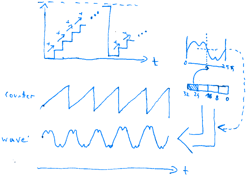
Next is the envelope generation. I'm using the popular ADSR envelope.
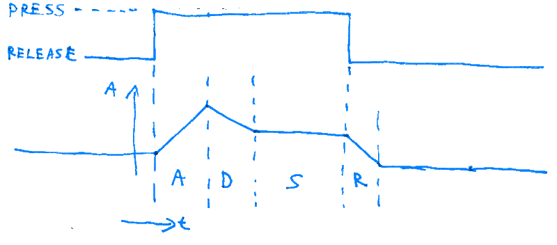
When the key is pressed, the amplitude is rising until reaching the max level. That's the Attack phase. Then it's falling back down, that's the Decay phase. The falling stops and the amplitude stays at a fixed level as long as key stays pressed. That's the Sustain phase. Finally after releasing the key the amplitude falls back to 0. That's the Release phase. The parameters A, D, R define the rates of amplitude change. The parameter S defines the sustain level. A trick question: what should happen when the key is released before the amplitude could fall to The S level?
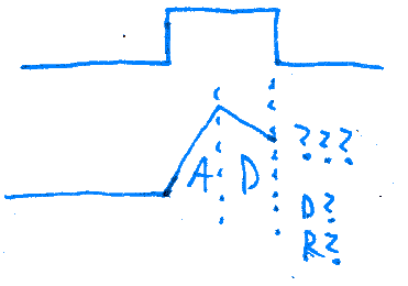
Which rate should be used to decrease the amplitude? D? R? My answer: above S I use the faster one from the both, below S I use R.
The envelope generation is done as a simple state machine. In each iteration the conditions for the ADSR phases are checked and the appropriate ramp is applied or not.
Challenge: Between the interrupts there is not enough time to calculate all this for all 12 channels. Time for a creative solution. I notice that the rates of change for the amplitude are much slower than the waveform. So I could get away with calculating them slower. I split the task into 2 subtasks. The first one is the state machine, the decisions when to move to which ADSR phase. The second subtask is applying the appropriate amplitude ramps for each phase. I made the first subtask 12 times slower. In each iteration the ADSR state machine is checked for only 1 channel. In next iteration for next channel and so on. So for each channel the ADSR state machine is updated avery 12 interrupts. The second subtask, actually increasing or decreasing the amplitude based on current ADSR phase is still performed for all channels in each iteration.
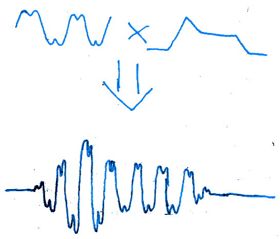
When the waveform and amplitude are ready, they are multiplied together and the result is the channel's output value. All 12 outputs are added together and the result goes to the DAC.
Generating the signal this way involves resampling the same waveform to all needed frequencies without any filtering. This can lead to aliasing and other artifacts, especially on higher notes when the waveform has sharp transitions. My answer to this: I'm aware but I don't care.
Such things are a big problem when reproducing sound. Here, however, the device is producing an entirely new sound. And I decided that all those effects are just normal properties of the produced sound (with currently used settings) If that sounds good or bad is a subjective opinion. If you like what you hear, then great. If you don't like, try finding other settings which will sound better. That's all.
There is a 12 tone polyphony, but it is possible to press more than 12 keys at once. In such cases always the last 12 pressed keys will play. In normal circumstances this should not be a problem unless you use extra hands or abuse the sustain pedal.
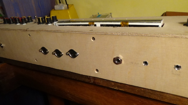
Audio output
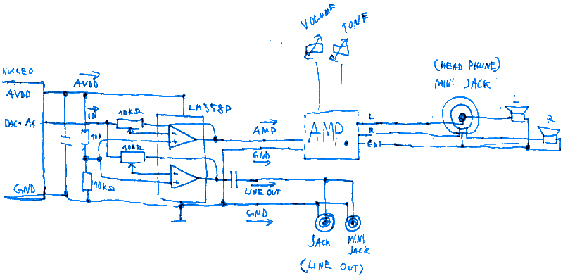
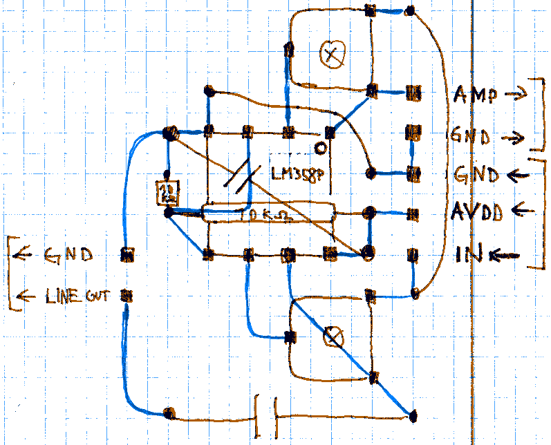
The audio signal leaves the DAC. It is split in 2 and enters the dual opamp LM358P. There its level is adjusted (regulated by on-board potentiometers). One opamp output goes to the LINE OUT connectors (jack and mini jack).
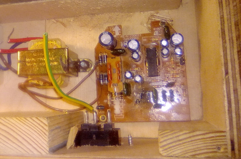
Other opamp output goes to the actual main amplifier. From the amplifier the signal goes to the earphone mini jack connector and to the speakers. When earphones are connected, it disconnects the speakers. The speakers and the amplifiers I took from an old PC speaker set. I had to unsolder the potentiometers from it, to put them on the top of the case.
MIDI
At some point I decided that I want to try adding a MIDI interface to the instrument. I was very positively surprised because I soon realised that this was much easier than I was afraid of.
A good source of information about MIDI is this page (http://midi.teragonaudio.com/tech/midispec.htm). A lot is explained there in a very understandable way.
I implemented a very limited subset of MIDI. These are the messages that the device supports:
- Reset
- Note Off (but ignoring the velocity parameter)
- Note On (but ignoring the velocity parameter if not 0)
-
Controller, supporting the following controllers:
- Sustain Pedal
- All Sound Off
- All Controllers Off (the 'all' controllers being the pedal only)
- All notes Off
From the user interface it is possible to configure on which of the 16 channels should commands be accepted. It is possible to select one channel or all channels. It can be also selected to which channel it should send commands too.
It is possible to disable controlling the sustain pedal by MIDI. That's because many MIDI files that I have insist on playing with the pedal constantly on which is not always what I would want.
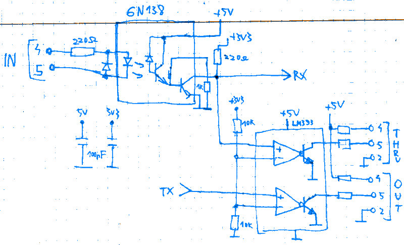
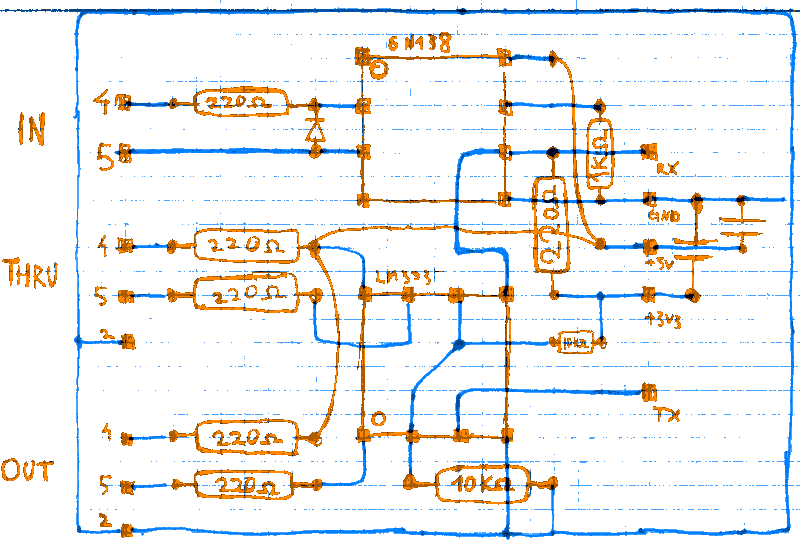
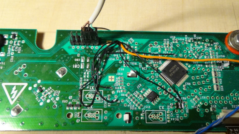
The hardware part of the interface is actually not difficult either. It looks kind of like this:
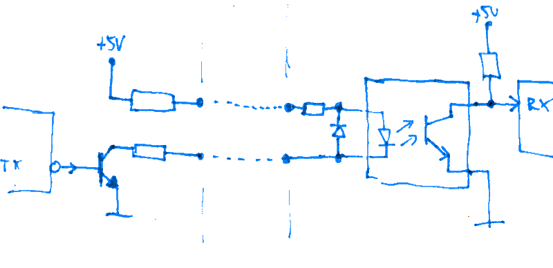
Just a regular UART but connected differently, optically isolated. The only challenge here is finding a fast enough optocoupler. The baudrate of 31250 bits per second may seem strange at first until you realise that it's actually 1MHz divided by 32. My circuit looks like this:
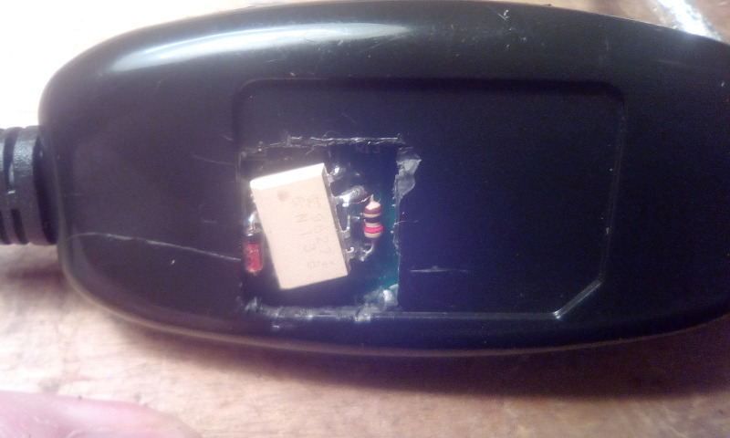
I bought an inexpensive MIDI to USB converter. I do not recommend buying this. Please don't buy it.
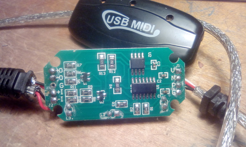
To reduce cost, probably, they replaced the optocoupler with a transistor. In such a way that when both the instrument and the computer are grounded it actually shorts the signal to ground, meaning that transfer to the computer is not possible.
I modified the circuit to fix this problem (also I fixed the disconnected LEDs).
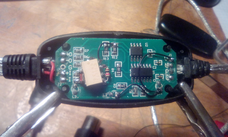
Unfortunately this was not the only problem. when sending the MIDI messages it often sends messages at wrong times (or starts at right time but waits between bytes), or sends invalid or incomplete messages. At first I thought that this was a problem with my instrument but then using a logic analyser I discovered that the USB adapter is guilty. Why does anyone even produce and sell such useless stuff wasting people's time and money?
I ended up using a simple serial adapter built around the FT232RL chip, following the instructions on this page (https://wiki.debian.org/MidiHardware). It worked perfectly.
Side note: when I play a MIDI file which has too many notes to be sent through the MIDI interface in real time the notes will arrive with delay because they are buffered between the software's MIDI output and the serial interface. This effect can be observed on the attached video at around 11:50.
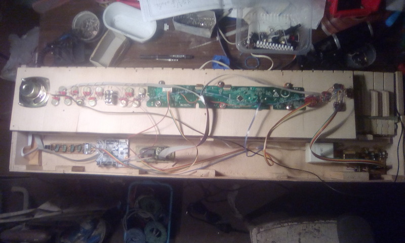
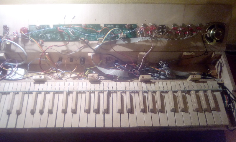
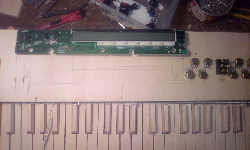
Case
The keyboard and the electronics cannot simply float in space. It has to be enclosed in some kind of case. There is not much to say about it. The walls and floor are made from 4mm plywood, supported by rectangular wooden blocks in some places.
Behind the springs I placed another plywood wall. between this wall and the springs I inserted some sponge to reduce the noise produced by the springs.
The back wall contains some connectors. The top wall contains speakers and elements of the user interface. Most components are attached to the floor from below by screws.
User interface
This is my design for the user interface:
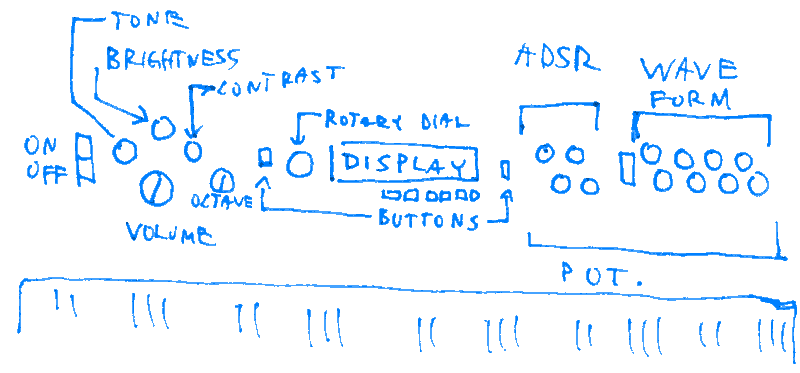
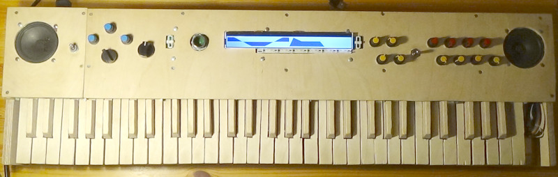
Most important parameters are accessible directly by switches and potentiometers so that they can easily be changed by the user in real time.
On the left, 2 potentiometers controlling directly the amplifier: volume and tone. "Tone" changes a filter which doesn't do much actually. Next 2 potentiometers adjusting the LCD display: brightness and contrast. Next the octave selector, already discussed before.
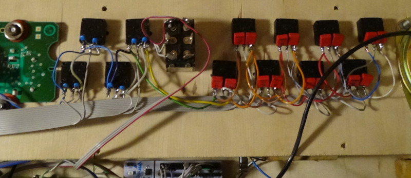
On the right, 1 switch and 12 potentiometers adjusting the waveform and envelope:
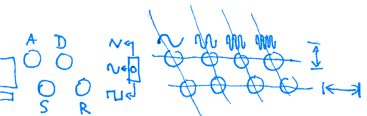
First 4 are adjusting the envelope. Each potentiometer is for one of the ADSR parameters. Next, a switch selecting the waveform type, 3 choices are possible, from top to bottom: triangle, sine, square. The waveform is composed from 4 components with different frequencies: 1F, 2F, 3F, 4F. Each component has a pair of potentiometers. the top one adjusts the amplitude, the bottom one adjusts the phase or for the triangle the slope angle.
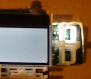
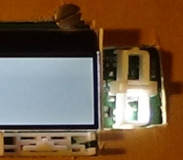
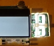
I also used a PCB board with display and buttons. Actually this is a UI board from a washing machine, which I reprogrammed.
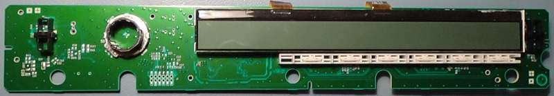
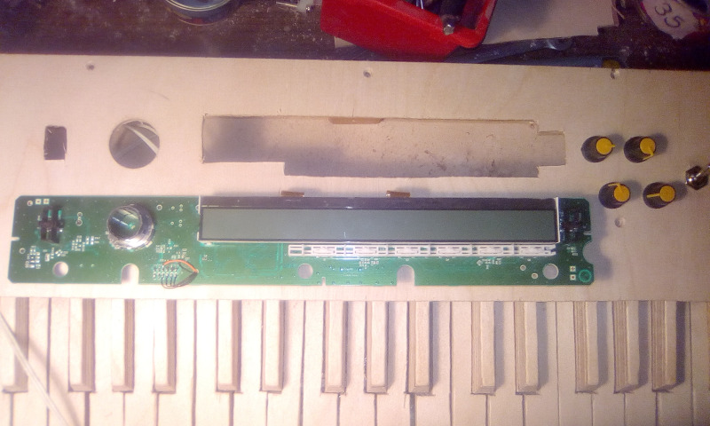
The board contains:
- a Renesas R5F104JG microcontroller
- a 1MB SPI flash memory
- a LCD display. 512 x 38 pixels. black and white or 2 bit grayscale.
- 6 buttons below and 2 buttons on sides.
- a rotary selector
- 2 UARTs
- a buzzer but I didn't use it.
Menu structure
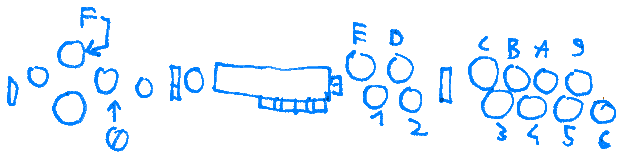
When describing the menu I will use the following names for buttons:
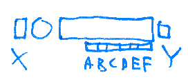
The buttons below are called A B C D E F from left to right. Th button on the left is X and the button on the right is Y.
waveform preview
By default the display shows a preview of the currently used waveform and envelope. Left half is for the waveform and right half is for the envelope.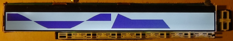
Buttons below the waveform (A, B) can lock or unlock the waveform. Buttons below the envelope (C, D, E) can lock or unlock the envelope. Button F locks or unlocks both at once. When waveform is locked the LED above button Y is on. When envelope is locked the LED below button Y is on. A locked envelope or waveform can not be changed by the potentiometers or switch. Button X goes to the options menu. Button Y goes to the voice preset selection menu.
voice preset selection menu
This menu allows selecting previously saved pre-sets of the waveform and envelope parameters. The display shows a "page" containing 6 choices. One above each button. There are 256 such pages. So there are 1536 possible choices.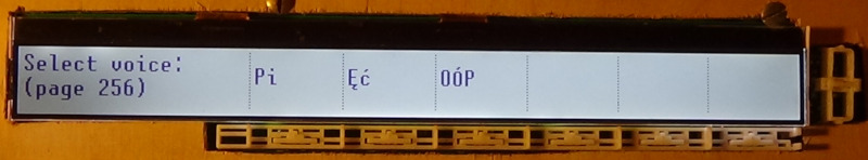
The rotary selector changes the currently active page. The buttons A B C D E F select a setting if there is one (a name is visible). Selecting a setting which is not available (no name above button) unlocks the settings so that values from potentiometers are used again. Button X goes to the options menu. Button Y goes back to the waveform preview.
options menu
As the name suggests this is a menu which allows to adjust some options. None of the options (except total reset, of course) are remembered when device is turned on again. For each option which has an edit screen, pressing the same button again or button X takes back to this option menu. All changes are applied immediately.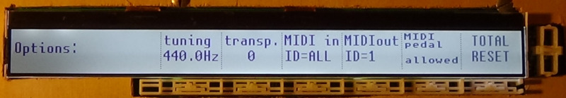
Button X goes back to the waveform preview. Button Y goes to the voice preset selection menu. Buttons A B C D E F change the available options:
-
tuning.
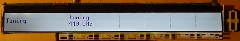
Rotary selector changes the tuning up or down by 0.1Hz The range is from 0 to 825.7Hz. (anything higher would cause an integer overflow when recalculating the counter increments for each pitch. -
transposition.
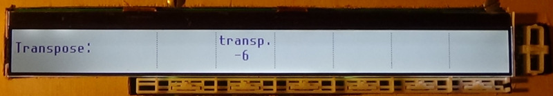
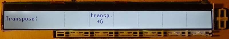
Rotary selector changes the number of semitones to transpose up or down. The range is from -6 to 6 which is half octave in each direction. If I want to transpose by +7 I can switch 1 octave higher and transpose -5 instead. -
MIDI IN channel ID
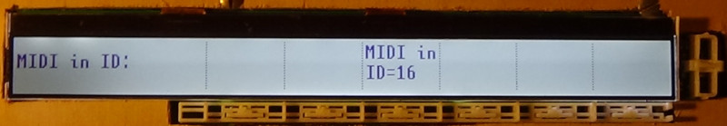
Rotary selector changes the which of the 16 channels to listen to on the MIDI input. The possible choices are from 1 to 16 or "ALL" which listens to every channel. -
MIDI OUT channel ID
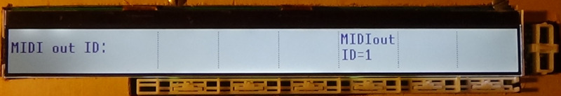
Rotary selector changes the which of the 16 channels to use on the MIDI output. The possible choices are from 1 to 16. -
MIDI pedal allowed or not
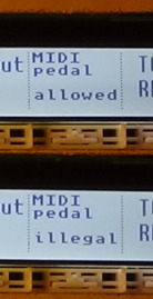
This changes if the MIDI commands to control the sustain pedal will be obeyed or ignored. -
TOTAL RESET
This reformats the flash memory which erases all presets. This takes a few seconds and then the device restarts.
saving a new preset
In waveform preview or in preset selection menu, when button Y is kept pressed for at least 680ms, the menu for saving a new preset is activated. It consists of 2 stages. Stage 1 is name input.
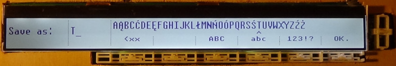
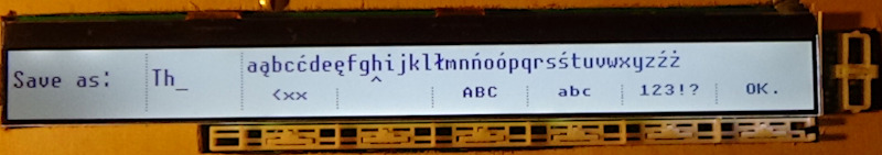
Name can be composed from characters from the Latin alphabet enhanced by Polish characters Ą Ć Ę Ł Ń Ś Ó Ź Ż, digits and some special symbols. Name consists of up to 4 rows of 7 characters.
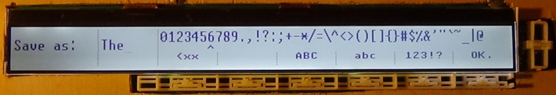
Rotary selector moves the cursor under the list of available characters. Button Y inserts the selected character into the name. Button A is backspace. Button B is space. Button C selects uppercase letters. Button D selects lowercase letters. Button E selects digits and symbols. Button F confirms the name input. (name must be at least 1 character long). Button X cancels name input.
When name is confirmed, comes the second stage, the choice where to save the preset.
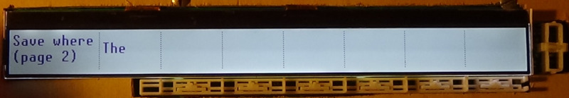
Button X returns to name input with name unchanged. Rotary selector changes to next or previous pages. Buttons A B C D E F select position on page to save the new preset. Saving happens immediately and if selected position occupied by existing preset it will be overwritten without warning.
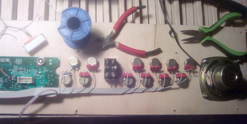
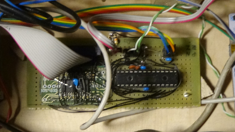
Analog input expander
The potentiometers are an important part of the user interface but the UI board can not read them directly. So I built an analog input expander (AIX). The microcontroller ATmega328P is connected to the potentiometers through the 74HCT4067D analog multiplexer. The software repeatedly changes the multiplexer's control pins, selecting which potentiometer is connected to the ADC input. (Actually the ATmega has multiple ADC inputs and can internally multiplex them. But only 6 and not 16.)
The software does not interpret the values in any way, it only sends them to the UI board. The software is thus very short and simple and even the ATmega328P microcontroller is much larger than needed for this purpose. I chose it simply because I already had it.
There are 16 potentiometers and the 74HCT4067D can handle 16 inputs. But only 14 are connected to it. The other 2 are connected directly to the amplifier.
I had to replace the potentiometers that I originally used because of quality problems. Some of them would sometimes lose contact which made the UI unusable.
AIX message format
The AIX (analog input expander) is repeatedly sending messages to the UI board using its UART. The baudrate is 115200 bits per second. I chose the message format to be made of case-insensitive readable text. This is the format:
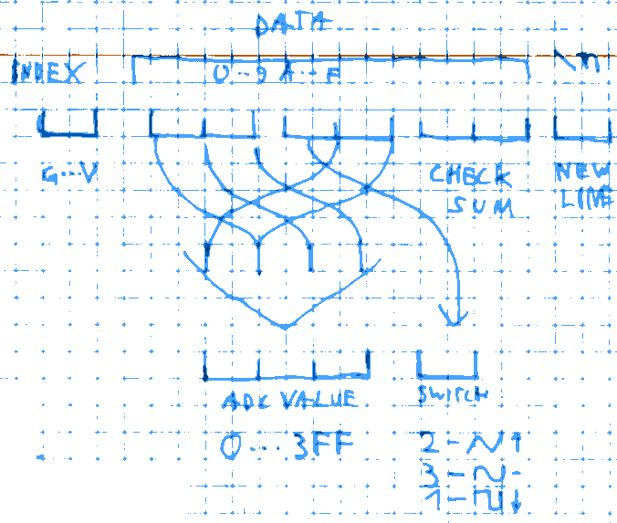
First character is the index, it tells which potentiometer's value is sent.
'G' means 0, 'H' means 1, and so on until 'V' which is 15.
Next are 3 data bytes represented by 2 hexadecimal digits each, upper digit first. So for example '1F' means 0x1F.
First byte contains the lower 8 bits of the ADC value.
Second byte's bottom digit contains the upper 2 bits of the ADC value and can take values from 0 to 3.
Second byte's top digit contains the switch position. There are 3 possible values. 2 is top position, 3 is middle, 1 is bottom.
Last byte contains the checksum. The sum of all data bytes including checksum, and the index must be 0. 'G' is counted as 0, 'H' as 1 and so on.
Last is the newline character.
For example "J451396\n" means that potentiometer 3 has value 0x345 and the switch is in bottom position.
UI request format
The format of the requests from UI to the main controller, and of the controller's responses is very similar to the AIX message format, only that there are different requests and and the message length is different for different requests. Again the baudrate is 115200 bits per second.
Again first character is the index, it identifies which request is being sent. It is a character from 'G' to 'M', case-sensitive. Uppercase requests get a value, lowercase requests set a value. List of all possible values:
- 'G' - get waveform
- 'g' - set waveform
- 'H' - get single sample
- 'h' - set single sample
- 'I' - get ADSR parameters
- 'i' - set ADSR parameters
- 'J' - get tuning
- 'j' - set tuning
- 'K' - get max tuning
- 'L' - get timing
- 'M' - get MIDI configuration
- 'm' - set MIDI configuration
The index is followed by some data bytes encoded again by 2 hexadecimal characters, case-insensitive. The number and interpretation of the bytes depends on request type. Some requests have 0 data bytes. Some contain 16 or 32 bit numbers. These are always in little-endian format. so 0x12345678 will be encoded as "78563412".
The data bytes are followed by a checksum. Again the sum of all data bytes and checksum and index must be 0. Here, however, only the index is counted differently, as the numerical value of the character is used. So 'G' is 0x47, 'g' is 0x67 and so on.
And finally, a newline character.
The controller must reply to each request even if the response has 0 data bytes, so that the UI always has a confirmation. Below I'll describe each request and response.
'G' - get waveform; 'g' - set waveform
The waveform is encoded as 256 signed 8 bit integers each representing one sample from first to last.The "get waveform" request is empty and response contains the full waveform.
The "set waveform" request contains the full waveform and response is empty.
'H' - get single sample; 'h' - set single sample
The "get single sample" request contains 1 unsigned 8 bit integer which represents the index of the sample to get. The response contains 1 signed 8 bit integer which is the sample's value.The "set single sample" request consists of 1 unsigned 8 bit integer which is the index of the sample to set followed by 1 signed 8 bit integer which is the sample's value. The response is empty.
'I' - get ADSR parameters; 'i' - set ADSR parameters
The ADSR parameters are encoded as 4 unsigned 32 bit integers in the following order: A, D, S, R. The values represent the actual value to increment/decrement the 32 bit envelope counter in each iteration, and are used by the controller directly with no further processing. The UI is expected to calculate the correct values by knowing the sampling frequency.The "get ADSR parameters" request is empty and response contains all ADSR parameters.
The "set ADSR parameters" request contains all ADSR parameters and the response is empty.
'J' - get tuning; 'j' - set tuning
The tuning parameters are encoded in the following way:First is 1 unsigned 16 bit integer which is the frequency for the A4 note. The unit is 0.1Hz so for example 440Hz will be encoded as "3011" (0x1130).
Next is 1 signed 8 bit integer representing the number of semitones to transpose up or down. Positive is up, negative is down. Allowed values are from -6 to 6.
The "get tuning" request is empty and the response contains all tuning parameters.
The "set tuning" request contains all tuning parameters and the response is empty.
'K' - get max tuning
The "get max tuning" request is empty and the response contains 1 unsigned 16 bit integer which represents the highest allowed tuning frequency for the A4 note, in 0.1Hz units. Currently the highest available value is 825.7Hz (0x2041),'L' - get timing
The "get timing reqest is empty and the response consists of 2 unsigned 32 bit integers.First is the controller's mainc clock frequency, in Hz.
Second is the divider to get the sampling frequency
Currently the main frequency is 32000000Hz and the divider is 720 which gives the sampling frequency of 44444.44444...Hz.
'M' - get MIDI configuration; 'm' - set MIDI configuration
The MIDI configuration is encoded as 3 unsigned 8 bit integers.First is the channel ID to listen to on the input.
Second is the channel ID to use on the output
Third decides if the sustain pedal can be controlled by MIDI input.
The channel ID has values from 0 to 15. 0 represents channel 1, 1 is channel 2 and so on.
For MIDI input a value above 15 means listening to all channels.
The sustain pedal MIDI control is allowed if the value is not 0.
The "get MIDI configuration" request is empty and the response contains all MIDI parameters.
The "set MIDI configuration" request contains all MIDI parameters and the request is empty.
'!' - incorrect request
If controller did not successfully receive a request, the response instead contains the '!' index and a single data byte which is an 8 bit unsigned integer. It contains a sum of the following error flags:- 0x01 - framing error on UART
- 0x02 - buffer overflow (controller didn't manage to process all bytes in time)
- 0x04 - incorrect checksum
- 0x08 - incorrect number of data bytes for request
- 0x10 - unknown request (incorrect index)
Flash memory file system
The instrument allows storing pre-sets for waveform and envelope parameters. There are 256 "pages" with 6 possible settings on each. Which gives the possibility os 1536 settings. These settings are stored on a 1MB flash memory. I had to develop a simple "file system" for this memory. I had to optimise for a situation where I can easily change a 1 to 0 but not otherwise.
The flash memory is divided into 256 sectors with size of 4kB. It's the smallest block that can be erased.
I divided the sectors into 8 "files" with size 512B.
byte 0 of each file is reserved.
byte 0 of file 0 in each sector (byte 0 of each sector) contains flags which indicate if a file is free or occupied.
Flag 0x01 represents file 0, flag 0x02 represents file 1, and so on.
Value 1 means file is free, value 0 means file is occupied (or deleted).
byte 1 indicates file type. These are the allowed values:
- 0xFF - free space
- 0xFE - reserved
- 0x54 - index 0
- 0xAA - index 1
- 0x3E - normal file (voice settings)
- 0x00 - deleted
Structure of a regular file (all numbers are little-endian):
- 0x000 - reserved (flags, as above)
- 0x001 - file type (as above)
- 0x002 - number of page where this setting is stored
- 0x003 - position on page, 0 to 5
- 0x004 - 0x007 - parameter A
- 0x008 - 0x00B - parameter D
- 0x00C - 0x00F - parameter S
- 0x010 - 0x013 - parameter R
- 0x014 - 0x02F - name, 28 characters, zero-terminated, no termination for full length name
- 0x030 - 0x0FF - unused
- 0x100 - 0x1FF - waveform, 256 signed 8 bit samples
There are also "index" files, occupying 2 sectors.
Each sector divided into 8 blocks of 512 bytes (just like regular files).
Each block, starting from byte 2 (0 and 1 reserved, flags, file type) contains 170 "records" with length of 3 bytes. That's 2720 records.
Each record represents 1 file, it's mapping the logical position ("page", and position on page) with the physical position (address in memory).
Format of record:
-
byte 0:
- bits 2-0: file position in memory sector, 0 to 7
- bits 6-4: position on UI "page", 0 to 5
-
bits 7,3: record status:
- 1 1 - free
- 1 0 - active
- 0 0 - deleted
- byte 1: number of memory sector
- byte 2: number of UI "page"
When file is created, the corresponding flag is set to 0, and new record is created. File type and content is set.
When file is overwritten, old file is deleted, new file is created in a free space.
When file is deleted, the file type is overwritten with 0, and the record in index is overwritten with 0.
When sector contains too many deleted files, all other files are relocated and sector is erased to be free again.
When file is relocated, old record is overwritten with 0 and new one is created.
When index contains too many deleted records, it is relocated and old index is erased.
Software
Below I share the software for all 3 microcontrollers. I share the source in the state after a successful compile so the archive contains also all output files. Do "make clean" to start fresh.
main controller
The software for the main controller is here: klavirko.tar.gz
It was developed using the SW4STM32 IDE (https://www.openstm32.org/System%2BWorkbench%2Bfor%2BSTM32). My files can be found in the "src" directory, released under the 2 clause BSD license. The project includes files added by the IDE like CMSIS, startup code, and so on. Those files are copyrighted by AC6, ST or ARM and are released under the 3 clause BSD license.
I wrote most of the code in C except for the main interrupt function which I wrote in assembly.
The software for the user interface is here: klavirko-ui.tar.gz
My files are released under the 2 clause BSD license. I developed this using the GCC toolchain for the RL78 platform.
Be careful! I accidentally installed the toolchain in wrong place. When I wanted to use the install script to remove it from there I managed to remove the entire /usr/bin directory by the script! Luckily, I was able to recover.
The toolchain itself is not enough to successfully compile a software. Required are also register definitions, linker script, startup code, and so on. The GCC toolchain does not provide them. So I did what is commonly done for projects like this. I downloaded the freely available e2studio IDE and used it (under Wine) to generate those files for me and copy to the project.
I deleted some of those files that I didn't need. I have rewritten some. But some were not changed much. Their license status is not clear. No license information in the files and nothing mentioned in e2studio's license agreement. I did not expect trouble for including them in my now freely available project:
Unfortunately, the wait turned out to be too long for me. So instead of continuing to wait I made my replacements for all those files. It's a task I wanted to avoid doing but I finally did it anyway.
The project also contains characters from the unscii font (https://github.com/viznut/unscii) which is in the public domain.
When compiling the project, actually 2 helper programs are compiled first. Those are used to generate header files used by the actual software. One generates a sine waveform, and one converts PNG files of the font into header file.
Because of the microcontroller's memory layout I had to split the code in 2 parts and put constant data in between. (to have them inside the so called mirror area). For this purpose I wrote a script which based on the sizes of code and data in the already compiled objects decides their placement and generates the actual linker script from a template.
I programmed the R5F104JG microcontroller using the rl78flash software (https://github.com/msalau/rl78flash) and a simple serial adapter.
rl78flash is a very nice free software. In the past I have identified and fixed or helped fix some bugs in rl78flash. But now I have a problem because the author no longer responds to issues on github and there are still things to fix. I am completely ready to provide the fixes by myself. I only would need answer to simple questions so that I know how to write the fix in such a way that my pull request will be accepted. But with no response I cannot. I don't want to create my own fork and split the project. I don't know what to do.
The software for the analog input expander is here: klavirko-aix.tar.gz
My file is released under the 2 clause BSD license. I developed this using the GCC toolchain for the AVR platform. The project contains a makefile, which is in the public domain, copied from WinAVR.
I programmed the ATmega328P microcontroller using avrdude and the AVT2994 programmer (https://sklep.avt.pl/avt2994.html?gclid=Cj0KCQiAoY-PBhCNARIsABcz773DpTB-KH__UMKe823MkLdLOgsrVrUiBl6VVusGxelrwQFBAcXiq2oaAjFGEALw_wcB). I had to make a custom programmer definition for avrdude to work with this. See avt2994-avrdude.txt for detail. When programming, important to also reprogram the fuse bits ("make program-fuse")
user interface
Anyway, to be 100% sure I asked Renesas a question about the status of such files, using their support ticket system. They told me to wait for an answer so I waited.
analog input expander